
Let’s explore how to reverse engineer a variable fillet from a polygonal mesh . . . When reverse engineering a physical model, radius values can be measured with various types of radius gauges. It can be somewhat of a challenge if the fillet face is worn, chipped, or distorted.

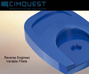
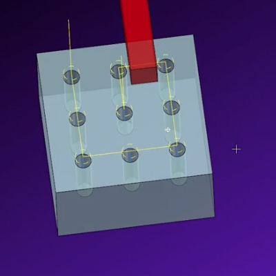
In addition, the task becomes more complex if the fillet is not constant, that is, if it varies along the edge like the mouse shown below.

How would you reverse engineer such geometry? A good software product that can be utilized for this type of work is Geomagic Design X.

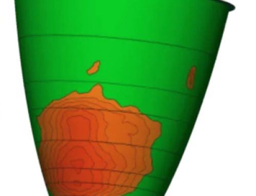
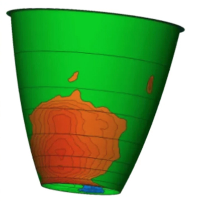
Above, you can see a polygonal mesh superimposed by the CAD model. If you add a fillet to the CAD model and click on Estimate Radius from Mesh you will get an averaged value that you can work off of. You can then set this to the desired value, in this case, a 1-1/2 mm fillet.

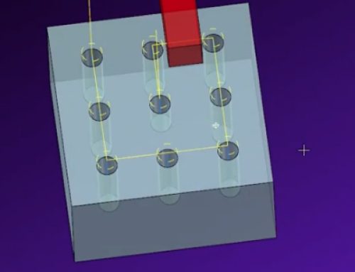
The real power is shown when you have a variable radius. After you pick the edges involved, simply match the CAD values to the averaged radius values along the mesh.

If you want to be more precise, type the values in directly. When satisfied, accept the command and the CAD model is complete.

As you can see, having the right tool for the job can assist you in taking a complex situation and resolving it with a few simple clicks. When it comes time to reverse engineering a variable radius from a scanned mesh Design X is the tool to use.
Please be sure to sign up for our 2 Minute Tuesday video series to receive tips and tricks like this one in video form every week. More info at the button below.


Leave A Comment